Portfolio
Here I go into (way too much) detail about projects I have been a part of or completed myself. This is the place where I get to talk as much as I like about what I like. It’s not meant to be a short read or a quick summary. I try to keep things from being too excessive but, I’m not always successful. :)
If you have questions or want to learn more, please contact me at dextercarpenter1@gmail.com.
Capstone Project
2023 - 2024
To earn an engineering degree at Oregon State University (OSU), every student must complete a Capstone Project toward the end of their education. The purpose is to give students an opportunity to work in their dicipline on a team and contribute to a project that emulates what one might experience in industry. The project I chose took me down a slightly different path than most, as I ended up co-leading an experimental sounding rocket team.

Context
But first, a small bit of history. OSU has a very large AIAA chapter(?)American Institute of Aeronautics and Astronautics with over ten seperate teams doing rockets, planes, drones, and more. OSU has famously completed in and won the SA Cup(?)Spaceport America Cup hosted by ESRA(?)Experimental Sounding Rocket Association in 2014 and 2016. However, with the COVID-19 pandemic and the passing of Dr. Nancy Squires many teams, including OSU’s ESRA team, were discontinued. Myself and a good friend of mine were approached by the OSU AIAA President to revive the team as both of us had immense leadership experience with FIRST Robotics. My friend was appointed as the Team Lead and I was selected to be the Treasurer since that role needed to be filled while still putting me in a leadership position. It was also beneficial since the work we did on the team would count for our Capstone.
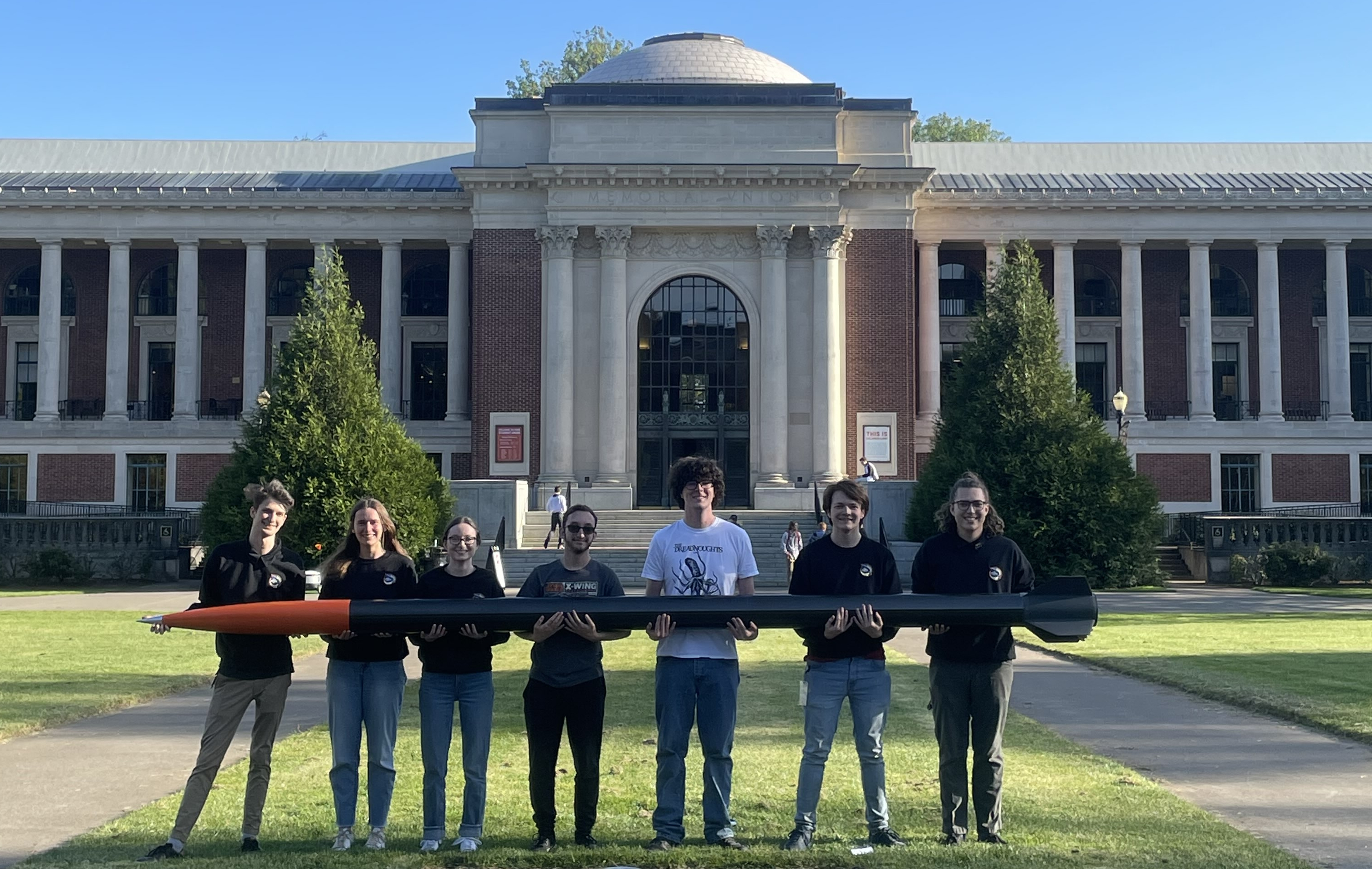
We agreed, recruited roughly five undergraduate (non-Capstone) students in the Fall, got accepted to the 2024 competition, and secured ourselves funding from the OSGC UTEAP(?)Oregon Space Grant Consortium Undergraduate Team Experience Award Program Grant. As I elaborate in a later section, I was the primary author for this grant as well as other technical documents. If you want to learn more about the grant, contact me. I don’t have a section for it specifically.
Category
 We made the decision in our application to compete in the 10,000ft SRAD(?)Student Researched and Developed
category. There are four categories. You can either aim for 10,000ft or 30,000ft. You're scored based on how closely you reach your target. Then you can either be an SRAD or a COTS(?)Commercial Off-The-Shelf
team. SRAD means you must create your own motor (propulsion system) and the freedom to put custom hardware elsewhere. In contrast, a COTS team must buy their motor from a commercial provider, and are slightly more limited as to what they could construct their rocket of. OSU has a history of mixing our own solid motors- in fact- OSU has one of the best-equipped motor mixing facilities in the US. While OSU has also previously competed in the 30k category, our team was brand new and very inexperienced. Thus the team made the decision to compete in the 10k SRAD category.
Design
By Winter, we had recruited 3 additional Capstone students for a total of ~12 team members, and began designing our rocket. This term was painfully slow. The team was still getting to know one another and synchronous time commitments from everyone was a challenge. However, we were able to get through a majority of our design process. I want to go into detail about the rocket design, specifically the fins, nosecone, air brakes, and composites which are the portions that I contributed most to. However, in order to keep this more digestable, I’ve given it it’s own seperate page.
Rocket Design Details →

I will talk briefly about our air brake system, of which I wrote all of the simulation and analysis required, and helped implement the control system. It was the biggest technical challenge and I contributed and considerable amount to it. We called it the Blade Extending Apogee Variance System (BEAVS) and you can read more about what I did specifically in a later section. The question arises Why try and brake the rocket? Wouldn’t you want to go as fast and high as possible? and the answer is no. For the competition, you are scored based on how close to 10k ft you get. Whether you overshoot or undershoot, both deduct points. Most teams will attempt to engineer their rocket to a specific thrust curve, a specific mass, and specific mass distribution to achieve their target. However, this requires extremely meticulous design. Some teams such as ourselves, intentionally overshoot their target and engineer air brakes to activate at a specified altitude and duration to lower their apogee to their target. We took it a step further and used a PID control system to actuate the brakes.
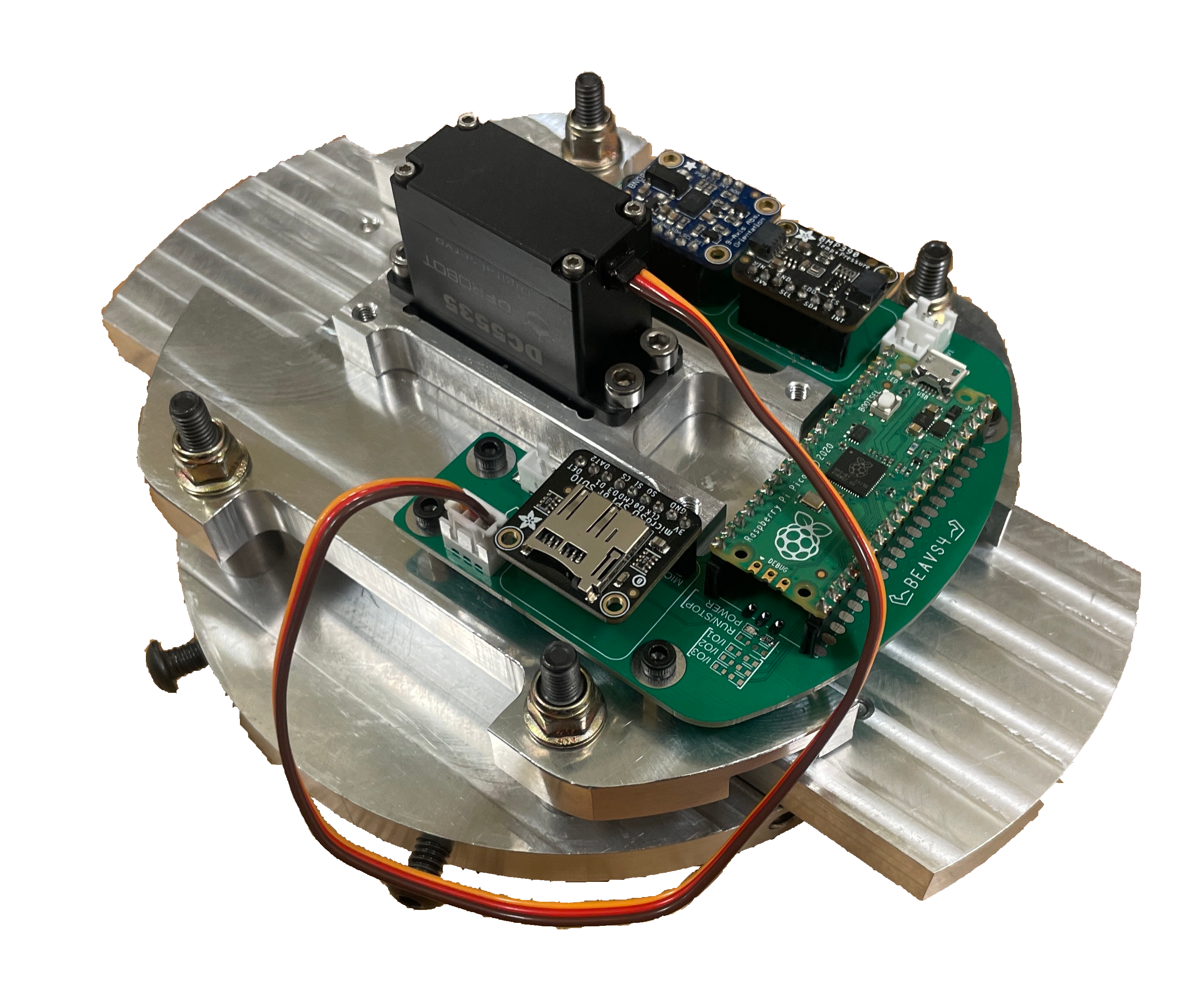
The physical BEAVS system
First Test Launch
By the end of the term in April we had a good idea of our design but, no progress on manufacturing the rocket. This was quite concerning as it put a lot of things to accomplish in the Spring before the competition in mid-June. With the proof of launch requirement rapidly approaching, myself and a few others put in 80-hour weeks to get the rocket constructed for our first test launch on April 28th. With a bit of luck, we had a successful launch and recovered the rocket with some minor damage (actual footage below).
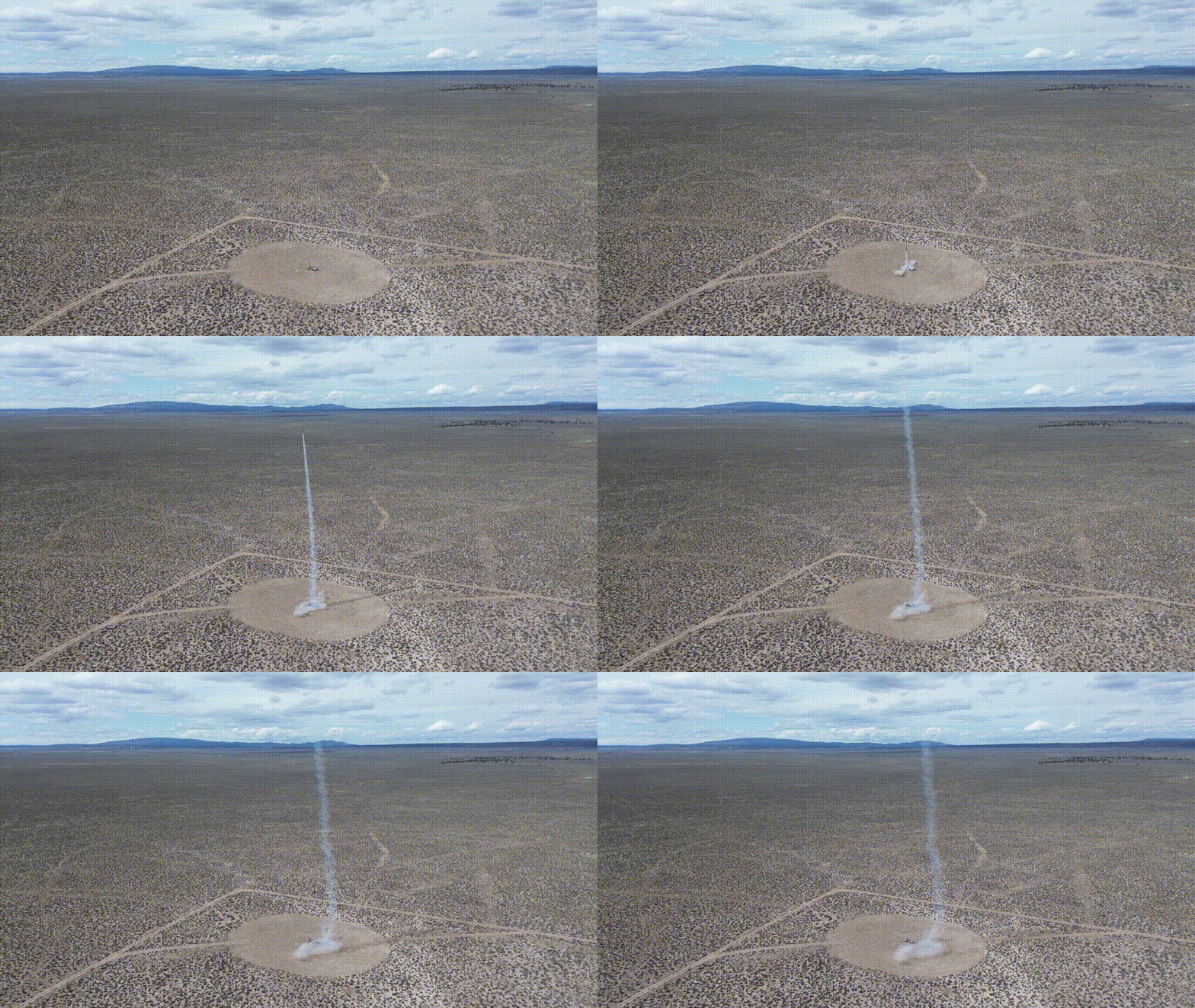
We sustained some damage during our recovery. This is a single-deperation, dual-deploy rocket. I talk more about what this is in the Rocket Design Details but simply, we have two parachutes. A drogue, that deploys at apogeeThe highest point in the development of the rocket, and a main, that deploys once the rocket passes ~1,500ft on descent. Our main parachute failed to deploy as the shock cord became tanged in the ejection charge wires. This caused the rocket to come down faster than desired, and caused damage to the upper section of the body tube, just below the nosecone, shown below.
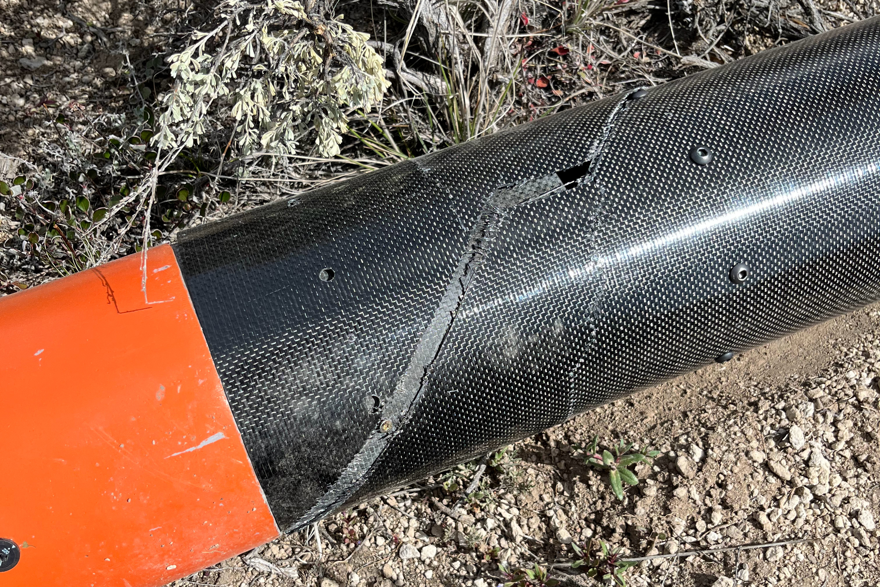
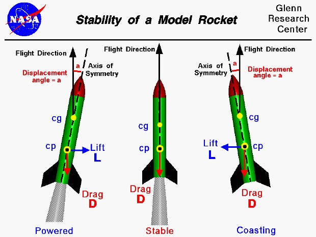
The initial solution was simple. Cut the cracked portion away. We cut about 14” off with only one small problem. However, this complicates things. Our rocket lost a lot of stability by reucing its overall length. Rocket stability can be simplified to the distance between the center of pressure (Cp) and the center of mass (Cg). A stable rocket has a center of pressure below the center of mass. NASA has a convient graphic to help illustrate this.
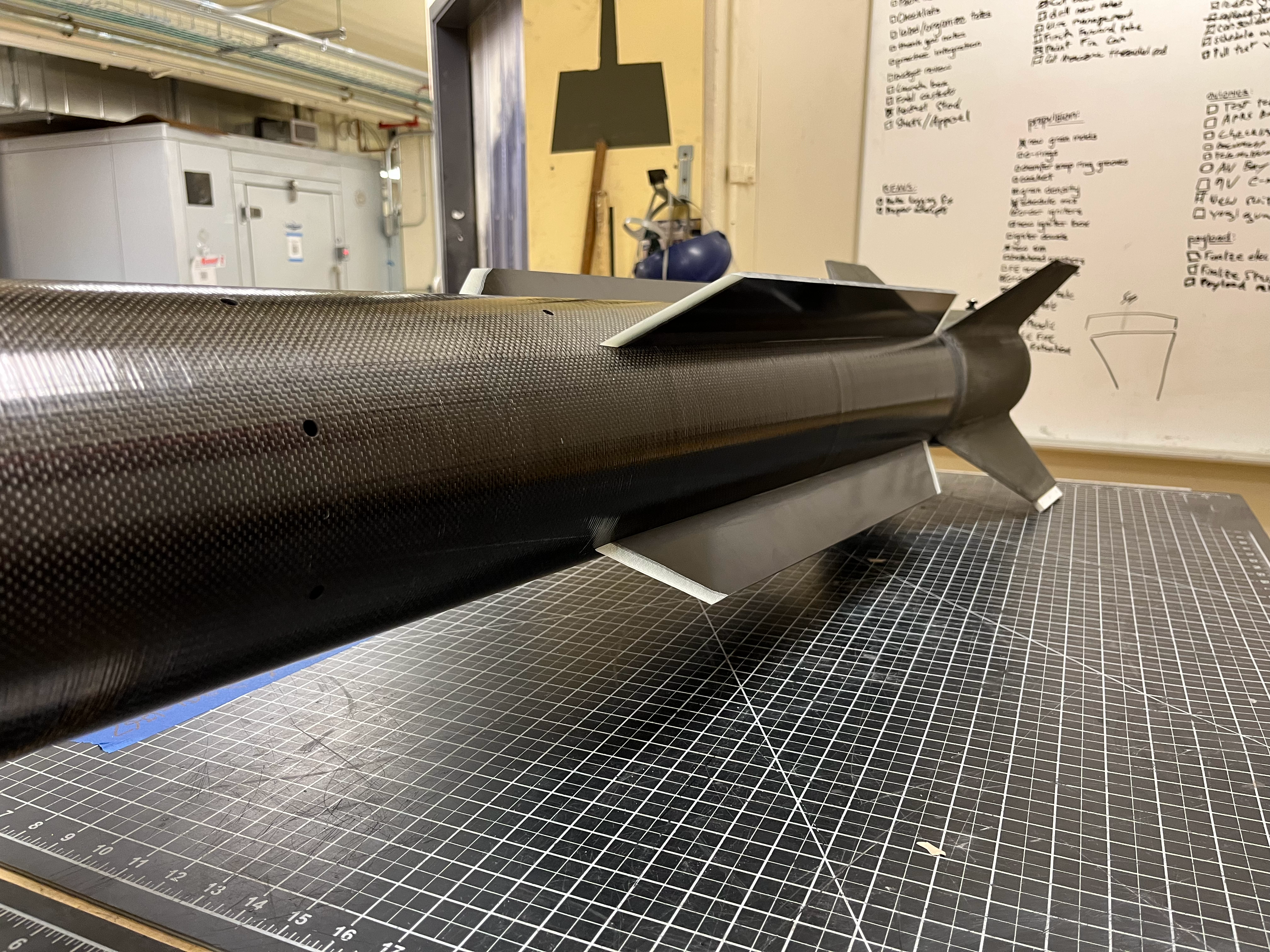
The damage lowered our Cg closer to our Cp, worsening stability. To solve this issue, we had to either reduce the mass on the lower half of the rocket (not feasible) or lower our Cp. Lowering the Cp can be done by increasing the fin size. Since the fins were already cured onto the airframe by a very labor intensive and complicated process that I talk about in the Rocket Design Details, it was not so simple to make the fins bigger. We had the idea of adding what we eventually called ‘strakes,’ some long and short fins that wouldn’t be susceptable to fin flutter, wouldn’t require a carbon fiber layup, and wouldn’t disrupt the flow over the original set of fins. In simulating the idea, we found that there were some geometries of the strakes that were very stable and very unstable. We realized we had to be very careful when choosing the geometry as to not pick one that would cause instability. An ideal course of action would have been to perform either Computational Fluid Dynamics or an experiment in a wind tunnel with a scale model. Then, test our design on a sub-scale rocket. However, we didn’t have time for any of these solutions. We talked to several professors at OSU and our mentors which gave enough insight to make the decision to proceed with our idea. We noticed that there appeared to be periodic critical lengths of the strakes that would cause tubulent flow across the fins (bad). We settled upon a geometry that sat in between the points and hoped for the best.
Spaceport America
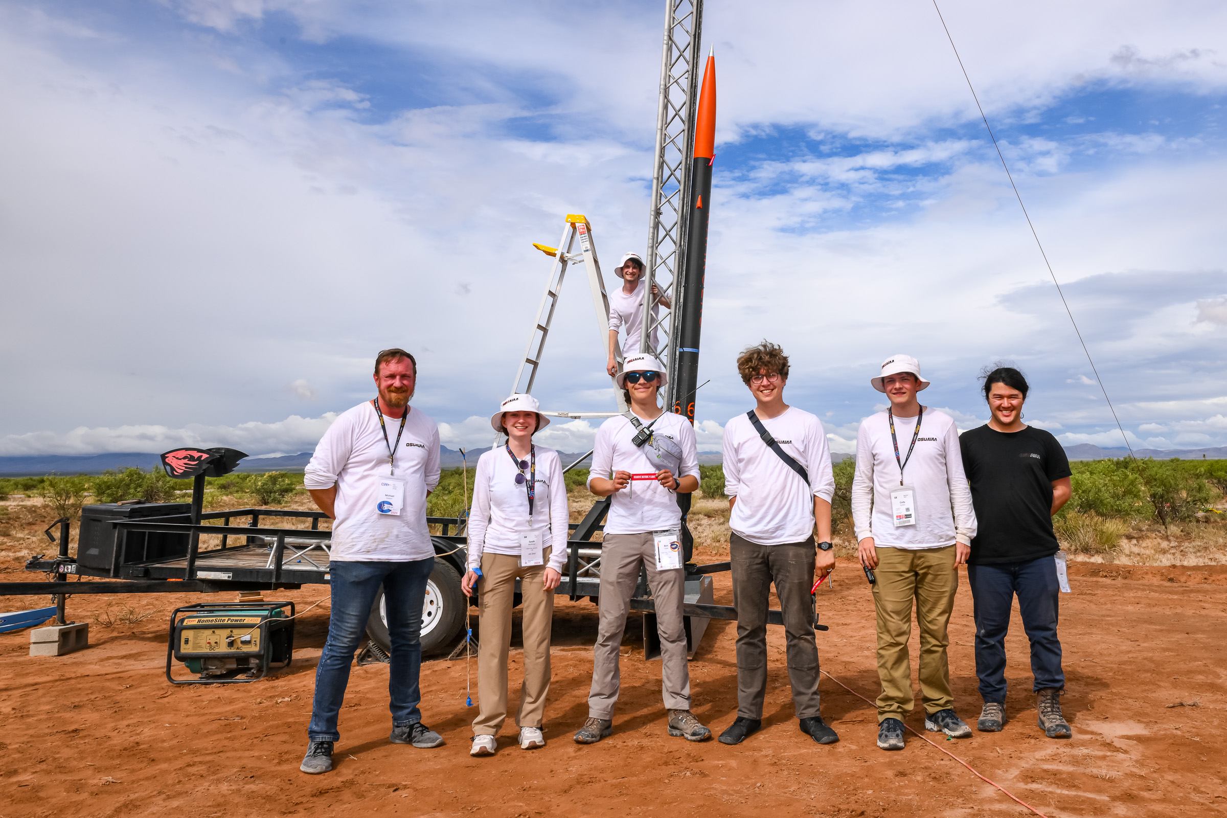
Soon the competition arrived, our team drove from Corvallis, OR to Las Cruces, NM where we stayed for the week-long competition. After 3 days of poor weather conditions, some integration problems, and delays from the event organizers, we finally were able to get off the ground!
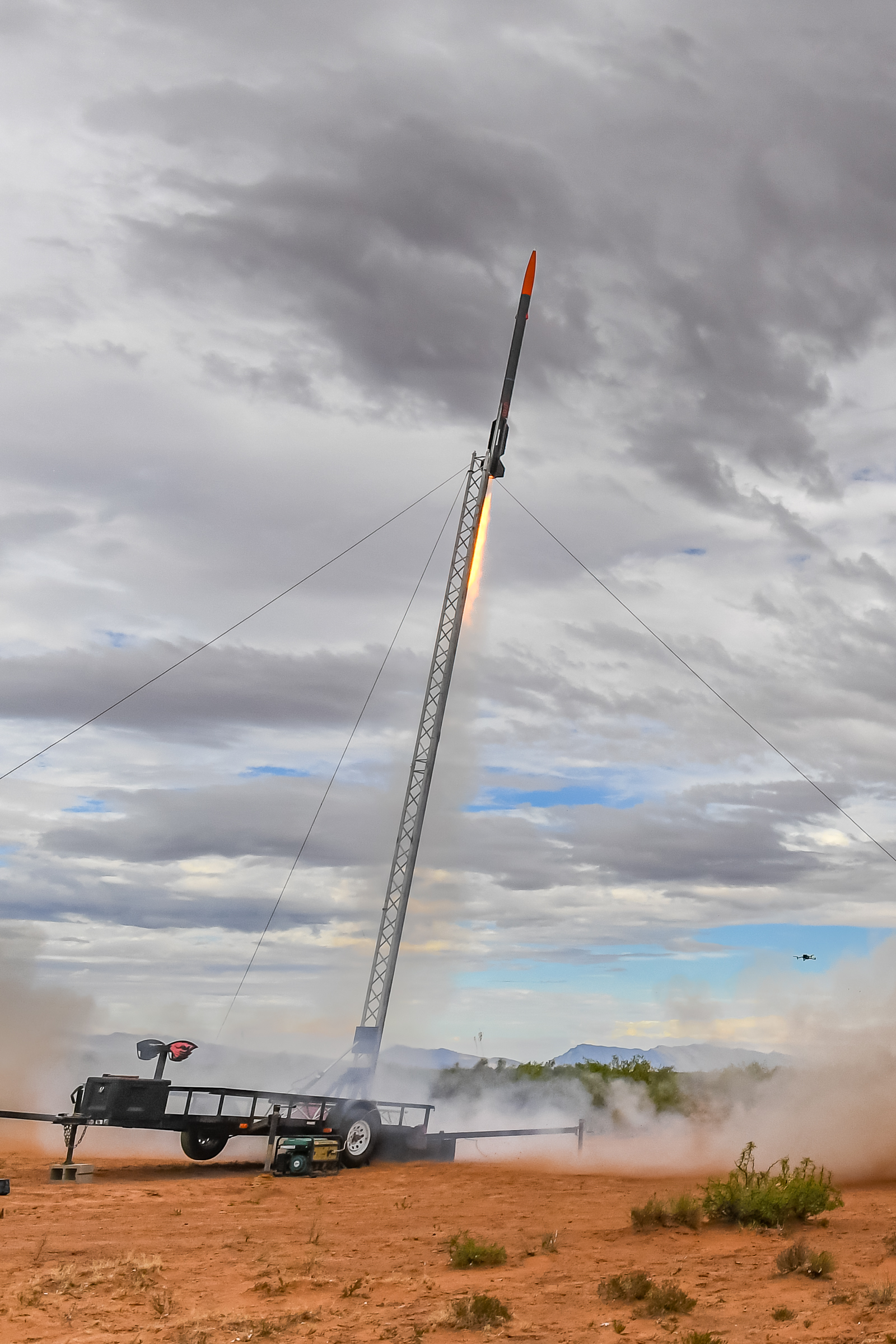
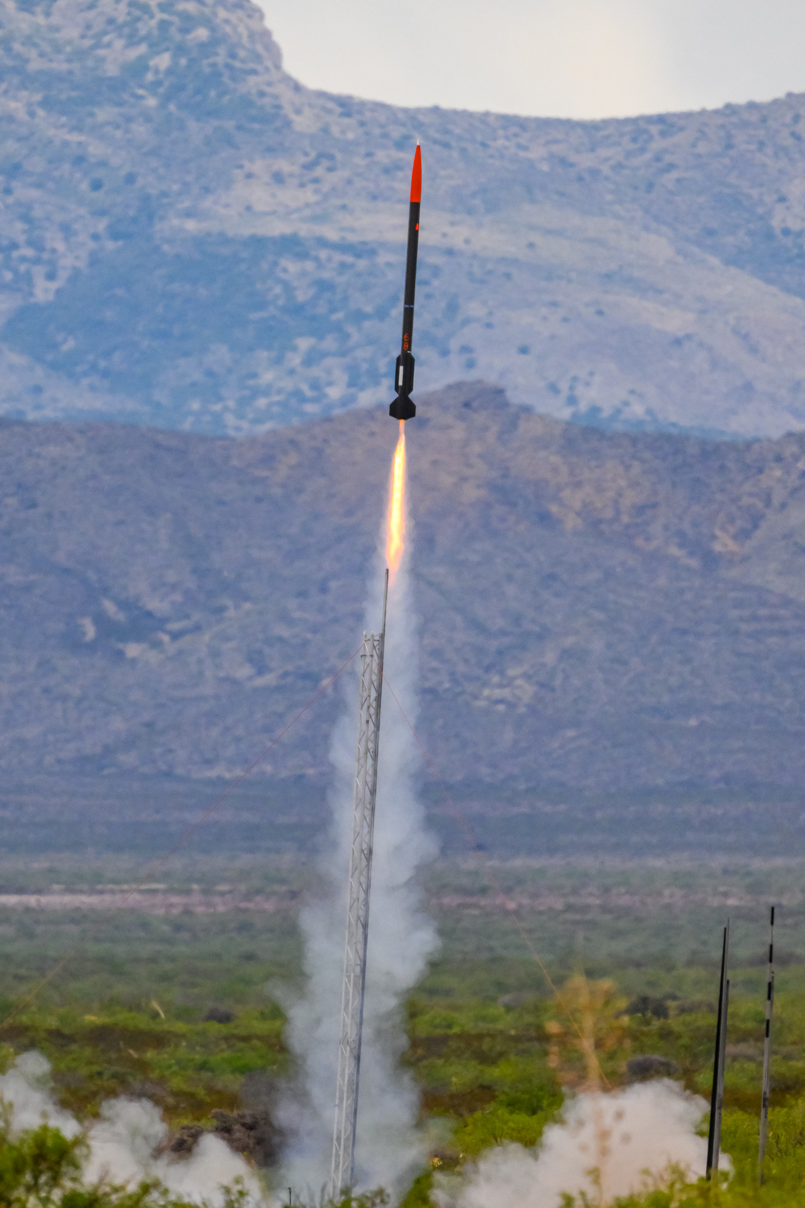
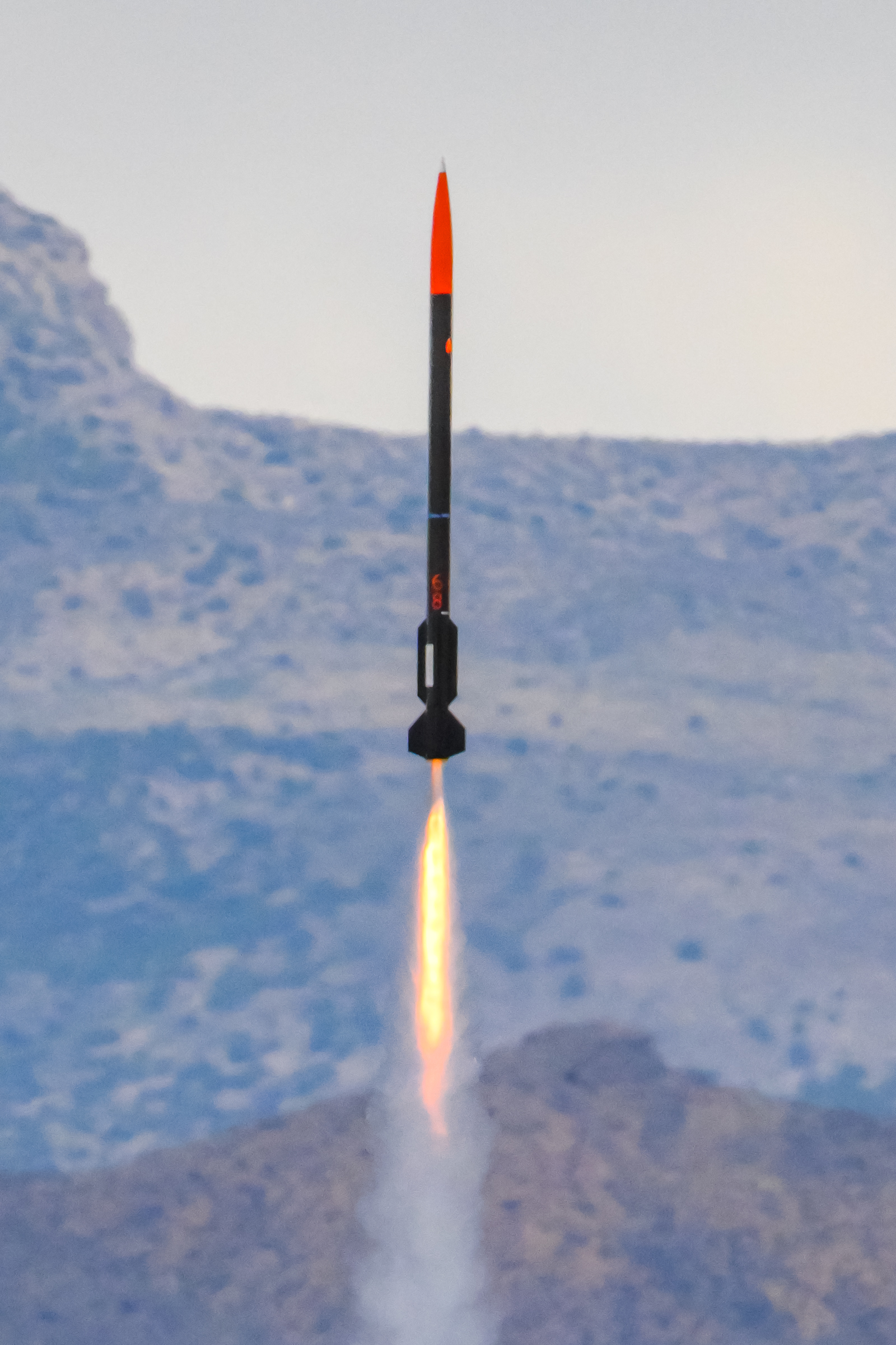
Unfortunately, our flight didn’t go as well we hoped. Our custom motor casing failed mid-flight and our motor lost thrust prematurely. However, it became significantly worse when our ejection charges failed to seperate our rocket, sending our rocket down ballistic. This was a rookie mistake and easily avoidable. Granted, we were a rookie team and were impressed with ourselves for getting as far as we did. Myself and the few others who graduated from the team felt extremely accomplished as we had laid the foundation for the team to continue to operate in years to come. The team this year was untraditionally almost entirely non-Capstone students. Only 4 of the 12 members attending the competition were seniors. Traditionally, the team is comprised of almost exclusively Capstone seniors. However, my colleagues and I intentionally laid the groundwork to enable the team to govern themselves, something we all belived to be very valuable.
Here is a fun recap video made by one of my teammates, Cody Eutsler.
BEAVS Simulation
2024
This project involed writing a simulation in MATLAB for the OSU ESRA Team (see above). The simulation is used to gain understanding of how the Blade Extending Apogee Variance System (BEAVS) will affect the rocket’s flight path. The simulation takes OpenRocket data export in conjunction with OpenMotor custom motors as a basis. The project is hosted on my GitHub.

The physical BEAVS system
Objectives
- Understand the total braking power of BEAVS given varying rocket designs
- Separation failure risk analysis
- PID control simulation
- Output data to BEAVS hardware to simulate flight (did not achieve)
The first objective was to understand the total braking power of BEAVS given varying rocket designs. Early in the development process the propulsion team needed to determine how large to make the rocket motor. To determine this, the team needed to understand how much BEAVS could theoretically reduce the apogee by. This was a very large first leap. To achieve this, the aerodynamic drag problem must be solved, a process for importing simulated rocket flight data into MATLAB must be written, and a solution to calculate how BEAVS’s change to the drag will affect the flight. All these problems are solved with the Control Range Graphic shown below.
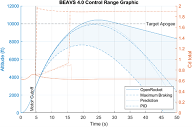
This graphic highlights the minimum and maximum BEAVS could lower the apogee by. The solid blue line represents the rocket’s altitude over time if no air braking occurs. This is equivalent to the direct data import from OpenRocket. The dashed blue line represents a maximum braking scenario and can be interpreted as the most that BEAVS could brake, if needed. The orange lines show the total coefficient of drag of the entire rocket over time.
Due to the location of BEAVS being on the lower (aft) section of the rocket, there is a high risk of separation failure. Separation failure occurs when the lower section has more drag than the forward section such that it causes the two sections to separate before it reaches apogee. This would be catastrophic for the competition. To mediate this failure mode, the MATLAB simulation calculates the force exerted by BEAVS and the force felt at the coupler between the two sections. This is represented in the following figure.
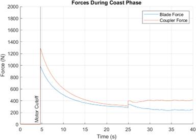
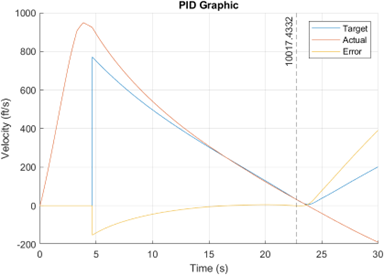
Due to the difficulty of testing BEAVS, it was required that the MATLAB simulation also implements a PID control system. The simulation was written initially with this functionality in mind. The simulation takes an input for the blade extension and calculates the force of drag it will induce. The system is iteratively solved using Forward Euler. At each time step, the PID function compares the current velocity to a target velocity using a height to velocity lookup table. Then outputs a desired blade extension amount. This desired blade extension amount is then fed to another function that evaluates whether the blades can be adjusted to the desired position. If possible, give a constant blade extension/retraction rate, the blade extension is set to the desired position. If the desired position is unreachable in the time step, it extends the most it could in the time step and returns that position to the Forward Euler iterator. Using this, Kp, Ki, and Kd values can be found with manual tuning. The following figure shows the error in velocities over time given a sample initial data set.
ESRA Project Technical Report
2024
As part of my work on OSU ESRA (see above), I was the primary author of the Project Technical Report for our team. I orchestrated the entirety of the report, writing a prodominant portion and delegating the remainder of sections to my fellow team members. The report “overviews their project for the judging panel and other competition officials” and therefore provides a fully comprehensive document of the entire project. It is worth 20% of the final score for the competition.
Our team’s Technical Report placed 29th out of 121 teams, scoring 183.7 of the 200 possible points. This is verifiable with the Final Scores on soundingrocket.org.
TwinCAT Conveyor Problem
2024
This was a 2-day project in which I learned Beckhoff’s TwinCAT 3 XAE and created a hypothetical solution to a problem for a job interview. I had no prior experience with Structured Text or Pascal prior to this!
Objectives
- We have an conveyor with 4 buttons Start Stop AND E-Stop AND Reset.
- When system starts it shouldnt do anything until reset.
- Starting it should speed up to a RUN_SPEED, over ACCEL_TIME and maintain.
- If stop is Pressed speed should decrease to 0 over DECCEL_TIME.
- If E_Stop is Pressed speed should go immediately to 0.
- Before resuming operation after E-Stop, the system should require a reset.
OPEnS Lab FloDar Project Lead
Jan 2021 - Oct 2022
At Oregon State University’s Openly Published Environmental Sensing Lab (OPEnS Lab), I contributed to the development and deployment of FloDar, a low-cost sensing system designed to monitor groundwater discharge and its properties. This project, conducted in collaboration with the Oregon Department of Transportation and the Oregon State College of Forestry, addresses the need for quantitative data on groundwater removal systems, which are crucial for landslide mitigation and infrastructure safety.

Responsibilities and Contributions
- Maintaining GitHub Repository: I ensured that our GitHub repository was consistently updated with the latest documentation, code, schematics, and images. This was vital for open-source collaboration and maintaining transparency with stakeholders.
- Facilitating Communication: I played a key role in fostering effective communication with stakeholders and lab management. This included regular updates, clarifying project goals, and ensuring that all team members were aligned with the project’s objectives.
- Meeting Preparation and Coordination: I organized and prepared for group meetings, including drafting weekly reports, updating project timelines, and gathering relevant data. I also coordinated schedules for field deployments and build parties, ensuring smooth logistical operations.
- Project Management: I maintained the project checklist and timeline, keeping track of milestones and deadlines. I went out of my way to do research and find a project management software to help myself stay organized. I was able to monitor tasks and update a Gantt Chart.
Technical Achievements
FloDar was successfully installed at three hillside locations, with plans for expansion. The system measures flow rate, turbidity, and temperature at specified intervals, capable of handling over 700L/min with an uncertainty of ±7L/min. This system provides critical data for understanding groundwater dynamics and improving the maintenance and operation of drainage systems.
Through my work at OPEnS Lab, I gained valuable experience in project management, team coordination, and environmental sensing technology, all of which have deepened my understanding of engineering solutions for real-world problems.
FIRST Robotics Team Experience
2016 - 2019
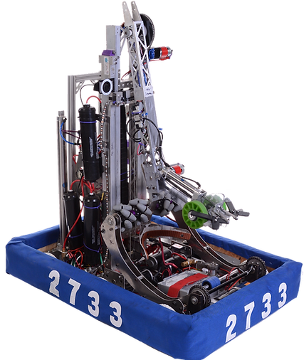
In high school, I became chronically involved with the FIRST® Robotics Competition (FRC) team. Each year FRC teams design, program, and build a robot from scratch and common set of rules to play in a themed head-to-head challenge. This was the beginning of my career in engineering and has taught me more about engineering and leadership than anything else. I still am friends with many of my teamates to this day. A few things that set our team aside from many others are being student lead, meaning the students were in charge of making the decisions and our mentors were a hands-off resource. We also had significantly less team members and funding, which provided an additional barrier to our success.
For the rest of this section, I’ll talk through what I did each year, sharing my story. I’ll then end with a more technical description of our 2019 robot Scorpion.
Freshman Year: Joining the Team
I joined our FRC team as a freshman, eager to immerse myself in the world of engineering and robotics. This initial year provided a foundation in teamwork, basic mechanical concepts, and the excitement of competitive robotics. Our robot did adequately this year, but our team had a very laid-back approach to the competition.
Sophomore Year: Build Lead
In my sophomore year, I was appointed as the Build Lead. Under the mentorship of the Manufacturing Captain, I got my first glimpse into leadership and hands-on engineering. Our department was responsible for transforming designs from the Design Department into functional components for our robot. We began prototyping with wood and cardboard, allowing for quick iterations and testing. Once designs were more developed, we manufactured the final parts using aluminum. My primary contribution to the team was the ‘Shooter.’ This was a flywheel mechanism that launched wiffle balls roughly 15ft into the air to score them. Our team performed very poorly this year. At each of our competitions, we struggled to field a functional robot.
Junior Year: Co-Leading as Manufacturing Captain
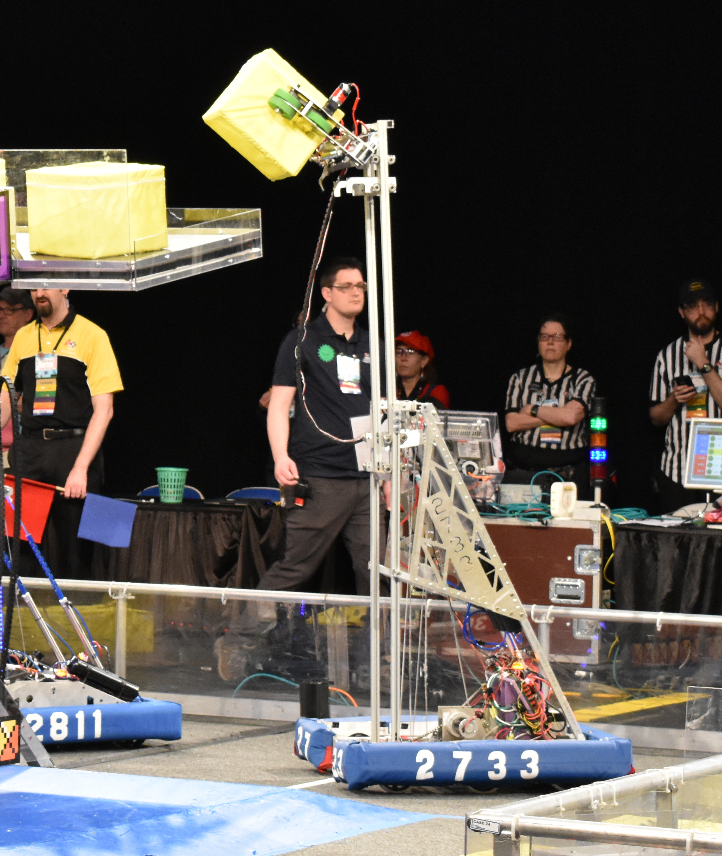
My junior year marked a significant step forward as I was elected to co-lead as the Manufacturing Captain. This role intensified my responsibilities and honed my skills in organization, communication, and managing a team under stressful environments. The challenge this year required a milk crate-sized cube to be placed on a scale +8ft into the air. Our team decided on using an ‘elevator’ mechanism, but were split on two different methods. We decided to work on both solutions in parallel. This ended up being a valueable lesson in both team dynamics and engineering. Our hard work and improved processes paid off, as we advanced to the District Championships for the first time in many years. This achievement was a testament to our improved design, iteration, and testing methods. The new set of leadership, including myself, had taken a vastly different approach to the team and after tasting success, were eager to do even better next year.
Senior Year: Team Captain
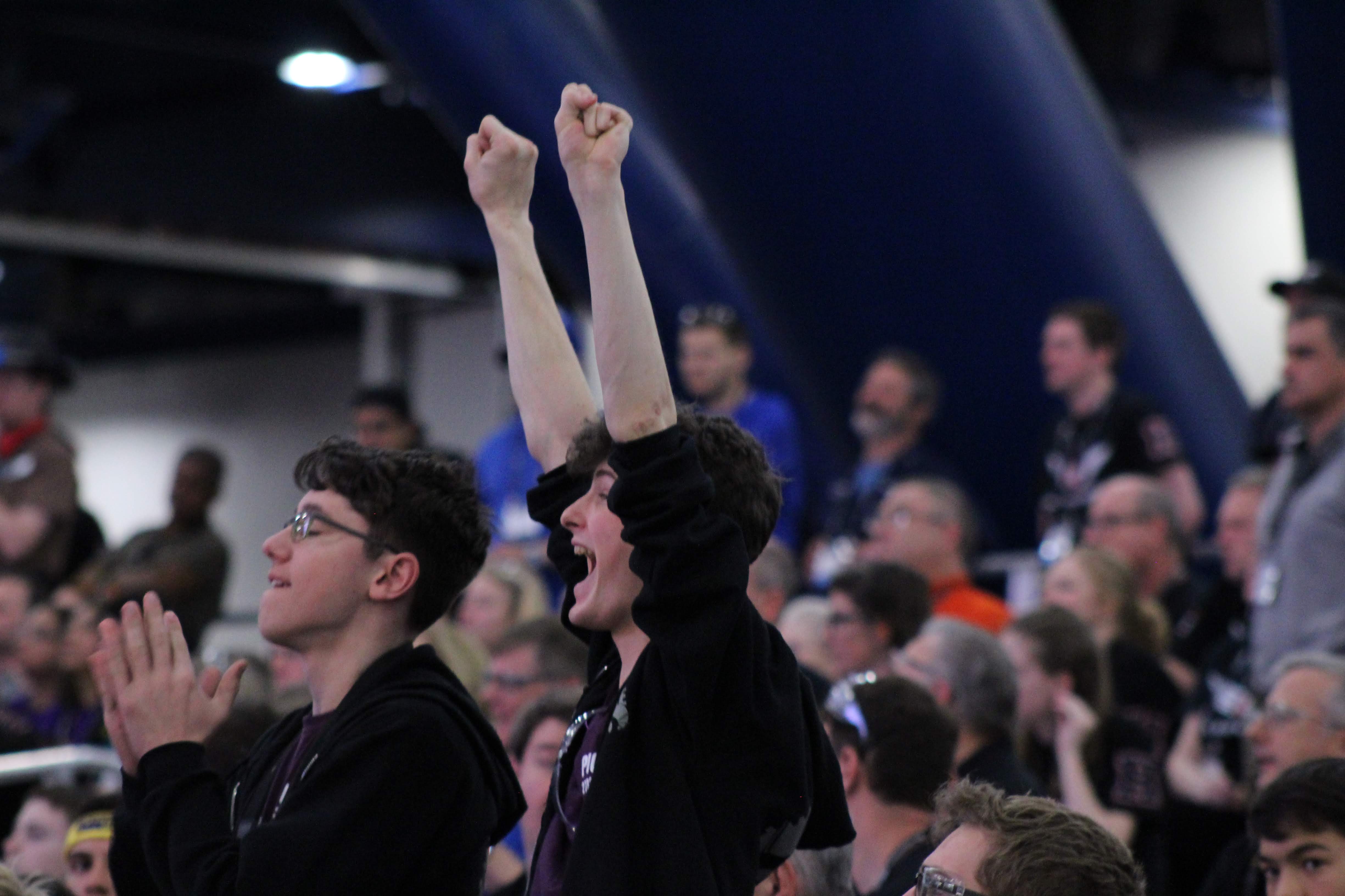
In my senior year, I was honored to be elected as the Team Captain, co-leading the entire team. My focus on leadership, organization, and fostering effective communication among team members culminated in an exceptional season. We advanced to the World-level competition in Houston, TX, where we became finalists in the playoffs of our division. Our team’s journey ended only after a closely contested match with the eventual world champions.
Throughout my journey with the FRC team, I developed a strong foundation in engineering principles, leadership, and teamwork. These experiences have significantly shaped my approach to problem-solving and project management, skills that I continue to apply in my ongoing engineering endeavors.
Scorpion Design Details →
RingGame
2020
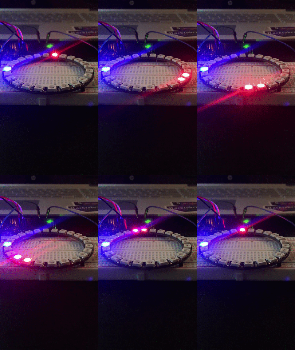
An Arduino-based arcade style game. Press the button when the lights line up to proceed to a faster level.
This was a one-day project. Using an Adafruit Neopixel ring (24), an Arduinio Uno, and a button I created a game where the objective is to press the button when the “runner” and the “selector” are aligned. If you are successful, you get a green flash and the runner gets faster. This proceeds until you miss, in which an animation plays and restarts the runner’s speed.
My goal was to make this as simple as possible, using just the NeoPixel and a button as the UI.
 Dexter Carpenter